Drone photogrammetry is a powerful tool for creating digital twins - highly accurate 3D models used in fields like construction, infrastructure, and environmental monitoring. However, achieving precision requires addressing key sources of error. Here's what you need to know:
- Accuracy Challenges: Measurement errors can arise from camera calibration, image overlap, georeferencing, and environmental conditions.
- Ground Control Points (GCPs): Properly placed GCPs significantly improve georeferencing accuracy. For example, using 5+ GCPs can reduce vertical errors to under 1 inch.
- RTK vs. PPK: Both positioning methods provide centimeter-level accuracy. RTK works in real-time but requires a stable connection, while PPK processes data post-flight and is better for remote areas.
- Camera Calibration: Ensures lens distortions and focal length shifts are corrected. Regular calibration and capturing images with high overlap improve results.
- Processing Techniques: Steps like bundle adjustment and filtering tie points refine models and reduce distortions like doming.
How to Assess the Accuracy of Your Drone Mapping? (YDQA EP 116)
sbb-itb-ac6e058
Ground Control Points and Georeferencing Accuracy
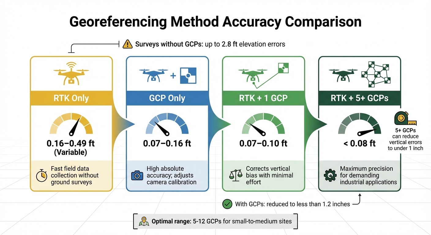
Georeferencing Methods Accuracy Comparison for Drone Photogrammetry
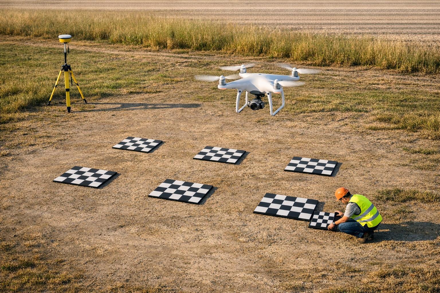
Ground Control Points (GCPs) are essential for translating drone imagery into precise real-world coordinates. They act as anchors to correct positional data, particularly in industrial settings like construction monitoring and infrastructure inspections, where even small errors can have significant consequences. Without GCPs, even RTK drones can experience vertical shifts of several decimeters, leading to inaccuracies.
By providing reference coordinates, GCPs address internal biases and elevation errors that often arise with direct georeferencing methods. A study from the Czech Technical University in Prague revealed that surveys without GCPs had systematic elevation errors of up to 2.8 feet. In contrast, incorporating GCPs reduced these errors to less than 1.2 inches. These findings highlight the importance of strategic GCP placement for improving model accuracy.
GCP Placement Guidelines
The placement of GCPs greatly influences the accuracy of georeferencing. Research from the University of Madras suggests that placing 4–5 GCPs at the perimeter corners provides strong geometric constraints, achieving accuracy levels similar to denser networks of 8–11 points.
Vertical placement is just as critical. In a 2019 survey of a 1-hectare parking lot in Monrovia, California, a team used a DJI Inspire 2 to demonstrate the impact of GCPs. Using five or more GCPs resulted in a vertical RMSE of 0.026 meters (~1 inch), compared to 0.055 meters when relying solely on PPK. To optimize results, GCPs should be placed at varying elevations, such as ridge lines, gully edges, and low points, to provide 3D constraints.
Additionally, including a central GCP helps prevent systematic vertical bias. For the most accurate measurements, GCPs should be recorded using GNSS-RTK receivers, ensuring sub-centimeter precision, which surpasses the resolution of the imagery itself. Proper distribution of GCPs not only enhances calibration but also strengthens the fidelity of digital twins.
How GCPs Improve Digital Twin Accuracy
GCPs significantly enhance the precision of digital twins, making them more reliable for critical applications. Well-placed control points can achieve horizontal accuracies of 0.5–1.0 GSD and vertical accuracies of 1.5–2.0 GSD. For instance, a site captured at a 0.8-inch GSD could achieve horizontal accuracy between 0.4–0.8 inches and vertical accuracy between 1.2–1.6 inches, meeting the high standards required for construction projects.
| Georeferencing Method | Typical Vertical Accuracy (RMSE) | Key Benefit |
|---|---|---|
| RTK Only | 0.16–0.49 ft (Variable) | Fast field data collection without ground surveys |
| GCP Only | 0.07–0.16 ft | High absolute accuracy; adjusts camera calibration |
| RTK + 1 GCP | 0.07–0.10 ft | Corrects vertical bias with minimal effort |
| RTK + 5+ GCPs | < 0.08 ft | Maximum precision for demanding industrial applications |
Research also shows that using 5–12 GCPs is sufficient for small-to-medium sites, as accuracy gains tend to level off beyond this range. This means infrastructure-grade accuracy can be achieved without an excessive number of GCPs. Platforms like Anvil Labs can host these precisely georeferenced 3D models, enabling teams to confidently take measurements and annotate with high spatial accuracy. This precision sets the stage for further advancements in project workflows.
"The RTK/PPK method of the georeferencing can provide data with comparable or even higher accuracy compared to the GCP approaches... [but] unless at least one GCP is provided, there might be biases in object coordinates, especially in elevation."
- Martin Štroner, Department of Special Geodesy, Czech Technical University
RTK and PPK Positioning Methods
RTK (Real-Time Kinematic) and PPK (Post-Processed Kinematic) systems build on traditional GCP-based georeferencing to make workflows more efficient. These methods provide centimeter-level accuracy, a huge improvement over the 10–16 feet offered by standard GPS. Both work by correcting GNSS data using a fixed base station or a network of reference stations, reducing errors caused by atmospheric interference. The main difference between the two lies in when those corrections are applied.
RTK applies corrections in real time through radio or cellular links, embedding precise coordinates directly into image metadata, which allows for immediate verification. However, unstable connections can compromise its accuracy. PPK, on the other hand, processes GNSS data after the flight, making it a better choice for remote or obstructed areas, though it requires extra processing time.
Both methods rely heavily on accurate lever-arm calibration, which measures the offset between the GNSS antenna and the camera's optical center. Additionally, hardware-based camera event marking is critical for achieving precise results. Proper calibration ensures the centimeter-level accuracy these systems are known for.
RTK vs. PPK for Drone Surveys
Choosing between RTK and PPK comes down to the conditions of your site and your workflow needs. RTK is ideal for connected, time-sensitive projects where immediate results are a priority and a stable link to the base station can be maintained. PPK, in contrast, excels in long-range surveys or areas where cellular coverage is limited, such as sites with tall buildings or dense tree cover.
Here’s a quick comparison of RTK and PPK:
| Feature | RTK (Real-Time Kinematic) | PPK (Post-Processed Kinematic) |
|---|---|---|
| Correction Timing | During flight (real-time) | After flight (post-processing) |
| Data Link Requirement | Constant connection needed (Radio/NTRIP) | No link required during flight |
| Reliability | Can be affected by signal drops | Unaffected by in-flight signal loss |
| Field Workflow | Faster, real-time geotags | Simpler setup; no live monitoring |
| Office Workflow | Minimal processing required | Requires additional processing |
| Typical Horizontal Accuracy | 0.4–0.6 inches | 0.4–1.2 inches |
| Best Use Case | Connected, time-sensitive missions | Remote or obstructed locations |
"RTK drones are constantly connected to a base station or correction service that helps to increase positional accuracy. This means that even while flying, the image locations are highly accurate and ground control is rarely needed to obtain accurate imagery products."
- ArcGIS Drone2Map Help
Both RTK and PPK significantly reduce the number of required GCPs compared to older methods. That said, it’s still wise to place a few checkpoints to verify the final model’s accuracy, especially for critical industrial applications.
Accuracy Results from RTK and PPK
Studies consistently show that both RTK and PPK achieve remarkable accuracy, with Root Mean Square Errors (RMSE) under 4 inches. This far surpasses the 10–16 feet accuracy of standard GPS.
In May 2024, researchers Zhuangqun Niu, Hui Xia, Pengjie Tao, and Tao Ke from Wuhan University tested a DJI Phantom 4 RTK by surveying a square and a building. Even without GCPs, they analyzed 71 spatially distributed checkpoints and recorded a vertical RMSE of just 2.2 inches. Their work demonstrated that RTK-equipped drones can meet the precision needs of large-scale mapping projects without relying on traditional ground markers.
In another example, a 2019 study by Conor McMahon, Omar E. Mora, and Michael J. Starek used a DJI Inspire 2 with a GeoCue Loki PPK system to survey a 2.5-acre parking lot in Monrovia, California. By processing data against a Continuously Operating Reference Station (CORS), they achieved a vertical RMSE of just 1.1 inches, proving that PPK can deliver survey-grade results comparable to dense GCP networks.
A team led by Joseph Cerreta at Embry-Riddle Aeronautical University compared RTK and PPK using an eBee X drone in southwest Arizona. They found no statistical difference in accuracy between the two methods but noted that accuracy dropped significantly when the base station was more than 10 miles away from the flight site. This underscores the importance of carefully placing the base station for both RTK and PPK workflows.
For RTK, it’s essential to monitor the "Fix" state during flights to ensure corrections are applied correctly. For PPK, make sure your drone is logging raw GNSS data and camera event timestamps. Regardless of the method, setting your base station on a known coordinate point ensures absolute accuracy, not just relative consistency between images. Platforms like Anvil Labs can host these precisely georeferenced 3D models, enabling teams to collaborate with confidence throughout a project.
Camera Calibration and Image Capture Methods
Even with highly accurate RTK/PPK positioning, poor camera calibration can introduce distortions that compromise the precision of digital twins. Calibration ensures that the camera's internal parameters - like focal length, principal point, and distortion coefficients - are correctly measured. These parameters directly influence how software reconstructs a scene. Without proper calibration, issues like the "bowl effect" or vertical drift can skew elevation measurements.
Pre-Flight Camera Calibration
Camera calibration focuses on determining intrinsic parameters such as focal length, the principal point (where the optical axis intersects the sensor), and lens distortion coefficients. These help correct common issues like "barrel" or "fisheye" distortion. Before flying, it's also essential to calibrate the drone's Inertial Measurement Unit (IMU) for stable flight, the compass for navigation, and the gimbal to reduce vibrations. Calibration can be done in controlled settings using tools like checkerboards or directly on-site using flight images and Ground Control Points (GCPs) to refine intrinsic parameters.
In June 2023, researchers Kalima Pitombeira and Edson Mitishita from the Federal University of Paraná conducted on-site sub-block calibration over a 12-hectare urban area in Curitiba, Brazil, using a DJI Phantom 4 Pro. Their work resulted in a horizontal RMSE of 0.222 meters and a vertical RMSE of 0.154 meters, significantly improving vertical accuracy compared to standard self-calibration methods.
Temperature fluctuations during flight can also affect the focal length. For instance, a 40°C increase can shift the focal length by about 3.1 pixels on a 35mm lens. To counter this, allow the drone to reach its operating temperature before calibrating the IMU and starting the flight. Regular recalibration is recommended every four to six months or after events like crashes, firmware updates, or lens changes. Using advanced camera models that account for focal length, principal point, and multiple distortion parameters can enhance terrain modeling accuracy by up to 70% in scenarios without GCPs.
Once the camera is properly calibrated, following best practices for image capture ensures even greater accuracy in your models.
Image Capture Best Practices
Calibration is just the first step. Capturing images with the right techniques is equally critical. Aim for at least 60% in-strip and 30% cross-strip overlap, though 80% forward and 70% lateral overlap are preferred for more precise results. Incorporating oblique imagery - angled shots rather than straight-down nadir shots - adds stronger geometric constraints, reducing camera pose drift and improving focal length recovery. A December 2019 study by Yilin Zhou and colleagues from the University of Paris-Est found that oblique images maintained 3D scene accuracy with an RMSE of 1 centimeter on control points, whereas nadir-only flights were more prone to focal length errors.
Using a double grid pattern with oblique angles is an effective way to counteract the bowl effect. Capturing images at varying altitudes - such as one strip at 30 meters and another at 70 meters - helps separate focal length and camera height correlations, improving vertical accuracy in flat terrain. Additionally, shooting in RAW format preserves original distortion data, offering more flexibility for post-flight corrections. For cameras with rolling shutters, select specific modes designed to minimize translational distortion.
When images are properly calibrated and captured, tools like Anvil Labs simplify collaboration and annotation, making the post-processing workflow more efficient.
Processing Techniques for Error Reduction
When it comes to reducing photogrammetric errors, advanced processing techniques play a key role, building on the groundwork of precise camera calibration and image capture. One of the most critical steps is bundle adjustment, which refines images by calculating 3D coordinates and camera parameters like position, orientation, and sometimes internal settings (e.g., focal length). This process minimizes the gap between observed and projected image points, solving the "exterior orientation" issue that affects subsequent steps like dense image matching.
Two main types of bundle adjustment are commonly used:
- Free-network bundle adjustment: This method computes parameters in an arbitrary coordinate system and later applies a 3D similarity transformation. While faster, it is less rigorous and more prone to distortions.
- Block bundle adjustment: Here, both 3D coordinates and camera parameters are estimated within a control point coordinate system, offering greater stability and reducing the risk of model warping.
Another key tool, self-calibration, extends bundle adjustment by treating internal camera parameters - like focal length and lens distortion - as unknowns during processing. For example, in a coastal landform mapping project, self-calibration achieved a horizontal RMSE of 3.2 millimeters. However, excluding oblique imagery reduced accuracy by about 3.3 millimeters horizontally and 4.7 millimeters vertically.
Before generating the final dense point cloud, it's essential to filter the sparse point cloud. Poor-quality tie points can be removed based on metrics like reprojection error, multiplicity, and intersection angles (ideally close to 90 degrees for better geometric stability). A real-world example of this is the 3D Optical Metrology Unit at Bruno Kessler Foundation in Italy. In 2020, they applied this filtering process to a dataset of the Modena Cathedral, refining image orientation and producing more accurate dense point clouds using a combination of terrestrial and UAV imagery.
Bundle Adjustment and Self-Calibration
Bundle adjustment is the backbone of photogrammetric processing. It fine-tunes the relationship between images and the 3D points they represent, adjusting camera positions, orientations, and - if using self-calibration - even internal parameters. The goal? To make the reprojected 3D points align as closely as possible with the original image measurements.
Self-calibration adds flexibility by adapting to specific camera and flight conditions. However, it has limitations. For instance, in nadir-only image blocks, it often misestimates radial lens distortion, causing "doming" errors where the surface appears artificially curved.
"Mathematically speaking, a bundle adjustment is a non-linear least-squares optimization problem on the simultaneous estimation of the 3D point coordinates of the points on the image and the external camera parameters, potentially including the internal parameters." - Arnadi Murtiyoso, ICube Laboratory
For challenging projects with poor initial values or low intersection angles, damping methods like Levenberg-Marquardt can ensure convergence. Additionally, the accuracy of Ground Control Points (GCPs) is critical. For example, decreasing GCP accuracy from 2 millimeters to 22 millimeters caused a model's horizontal RMSE to more than double, from 3.2 millimeters to 7.0 millimeters.
After fine-tuning camera parameters, removing weak tie points is crucial for reducing systematic errors and improving accuracy.
Correcting Systematic Errors in SfM Outputs
Systematic errors in Structure from Motion (SfM) outputs often manifest as large-scale distortions like doming or twisting in digital elevation models. These issues typically arise from inaccurate radial lens distortion estimates in near-parallel image blocks. However, adding oblique images to your flight plan can reduce these errors by up to two orders of magnitude.
"Systematic DEM error can be significantly reduced by the additional capture and inclusion of oblique images in the image network... [reducing] error by up to two orders of magnitude." - Mike R. James, Lancaster Environment Centre
Using convergent imaging geometry, where images are captured at oblique angles rather than strictly nadir directions, helps break the correlation between radial lens distortion and surface form. Research shows that oblique camera angles between 20 and 35 degrees significantly improve accuracy, even for consumer-grade UAVs. In high-relief areas, camera inclinations of 20 to 40 degrees not only reduce error magnitude but also minimize spatial correlation, as measured by Moran's I.
Spatial autocorrelation analysis using Moran's I is a valuable tool for detecting systematic error patterns. A Moran's I value near 0 indicates random error distribution, while values closer to 1 or -1 suggest systematic bias. This analysis helps verify the effectiveness of error mitigation strategies.
If oblique imagery isn't available, systematic errors can still be mitigated by running multiple bundle adjustments with varying radial distortion values to identify a "zero-doming" parameter for final reprocessing. However, the more reliable solution is to plan your flight with convergent imagery from the outset.
To further reduce errors, prioritize placing GCPs along the edges of your survey area and evenly distribute them across the site. This ensures a uniform 3D transformation and minimizes model warping. Once processing is complete, platforms like Anvil Labs offer tools for hosting, viewing, and analyzing 3D models. These tools make it easier to validate accuracy and share results with collaborators.
Conclusion and Practical Applications
Creating accurate digital twins involves tailoring error mitigation strategies to meet the specific demands of a project. Studies indicate that incorporating 5–8 strategically placed Ground Control Points (GCPs) and leveraging RTK/PPK positioning can cut Root Mean Square Error (RMSE) by 45–70%, while reducing field labor to just 12.9–30.7% of traditional methods.
Error Mitigation Summary
Error mitigation focuses on four main areas: GCPs, RTK/PPK positioning, camera calibration, and processing techniques. Field tests reveal that a small number of well-placed GCPs can achieve excellent accuracy, minimizing the need for extensive ground surveys. RTK and PPK techniques further enhance efficiency by streamlining field operations.
The interplay between these methods is crucial. High-quality GCPs improve camera calibration, while advanced camera models help offset lower-quality GCPs. A "Model C" configuration - covering focal length, principal point, and radial/tangential distortion parameters (K1–K4 and P1–P4) - balances precision and practicality for industrial applications without overfitting. For example, in August 2019, a team led by Omar E. Mora from California State Polytechnic University successfully mapped a 1-hectare parking lot in Monrovia, CA, using a DJI Inspire 2 drone and a local base station with a one-hour dwell time. They achieved a vertical RMSE of 0.026 meters while reducing field labor to just 12.9% of what a 9-GCP manual survey would require.
Understanding the distinction between relative and absolute accuracy is also essential for industrial workflows. Relative accuracy (usually 1–3 times your Ground Sampling Distance, or GSD) works well for internal tasks like excavation volume measurements or monitoring structural shifts. However, absolute accuracy - positioning data relative to the Earth - becomes critical when integrating with external GIS systems or legal boundaries. While standard UAV GPS units offer horizontal accuracy of 2 to 6 meters, adding GCPs can improve this to 2.5 times the GSD horizontally and 4 times the GSD vertically.
With these methods securing high accuracy, the next challenge lies in turning precise data into actionable insights through digital platforms.
Using Platforms to Improve Workflow
Once accurate digital twins are established, platforms like Anvil Labs help transform raw data into practical solutions for industrial site management. These platforms capitalize on refined error mitigation techniques to deliver operational insights. After capturing and processing photogrammetric data, the focus shifts to making it actionable for your team.
Anvil Labs offers a secure environment for hosting 3D models, point clouds, orthomosaics, and thermal imagery. Its tools enable point-to-point measurements on 3D models, eliminating the need to send personnel into hazardous areas like quarries or rooftops.
For ongoing site inspections, the platform supports multi-temporal alignment, allowing users to co-register new data with existing point clouds. This feature is invaluable for detecting changes in excavation volumes or structural integrity. Anvil Labs accommodates various data formats, including .laz and .las for point cloud alignment, and .tif (GeoTIFF DEM) for surface models. With cross-device accessibility and integrations for AI analysis and task management systems, the platform simplifies the workflow from data acquisition to decision-making. By combining precise error mitigation with advanced digital tools, teams can achieve high-quality models and streamlined operations, ensuring that photogrammetric accuracy translates into tangible benefits.
FAQs
How many GCPs do I really need for my site?
For drone surveys that demand high accuracy, 5 to 10 ground control points (GCPs) are usually enough. The key is to position them thoughtfully across the site, ensuring they account for variations in elevation. If you're working with larger or more intricate areas, adding extra GCPs can help boost precision.
When should I use RTK vs. PPK on a drone survey?
Use RTK (Real-Time Kinematic) when you need instant, centimeter-level accuracy during tasks like construction tracking or live monitoring. RTK processes corrections during the flight, which minimizes the reliance on ground control points.
Opt for PPK (Post-Processed Kinematic) in scenarios where real-time corrections aren't possible, such as areas with limited connectivity or when post-flight data processing is acceptable. PPK delivers precise results after the flight, making it ideal for tough environments.
What causes “doming” in photogrammetry, and how can it be prevented?
"Doming" in photogrammetry happens when radial distortion and inaccuracies in camera parameter estimation affect the final model. To minimize this issue, start with thorough camera calibration, ensuring lens distortion is corrected. Incorporating both nadir and inclined images into your dataset can also help balance distortion effects. Additionally, rely on precise ground control points or GNSS data to enhance model accuracy and reduce the risk of doming. These practices work together to produce more reliable photogrammetric results.
