Ground Control Points (GCPs) are essential for creating highly accurate maps and 3D models from drone imagery. They serve as physical reference points with known coordinates, helping to align aerial images with real-world locations. Here's why they matter and how they work:
- Accuracy Boost: GCPs reduce positional errors from meters to just a few centimeters, ensuring survey-grade precision.
- Industrial Use: Critical for construction, infrastructure management, and terrain analysis where precision is non-negotiable.
- Optimal Placement: Use 5–10 GCPs for most projects, placed strategically to cover the site and account for elevation changes.
- Measurement Tools: RTK and PPK systems ensure GCP coordinates are captured within 0.02 meters of accuracy.
Quick Tip: Combine GCPs with RTK/PPK systems for even better results, especially in projects requiring high accuracy or legal defensibility.
Want to learn how to set up GCPs effectively or see how they compare to RTK/PPK systems? Keep reading for detailed steps, placement strategies, and real-world examples.
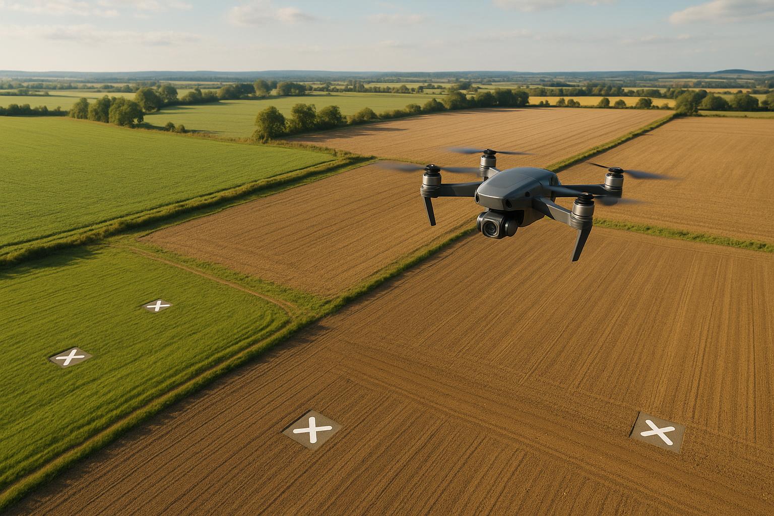
Data Capture Workflow: Understanding Ground Control for Drone Surveys
Planning and Installing Ground Control Points
Setting up Ground Control Points (GCPs) requires thoughtful planning and precise execution. Below, you'll find guidelines on designing, placing, and measuring GCPs to ensure accurate results.
GCP Design Guidelines
The physical attributes of GCPs play a big role in their effectiveness. Ideally, GCPs should be around 20 inches × 20 inches (0.5 m × 0.5 m) to remain clearly visible from typical drone altitudes. Use high-contrast colors like black and white or yellow and black, and opt for a matte finish to reduce glare and boost visibility.
For durability, choose weather-resistant materials such as:
- Vinyl flooring tiles secured with construction adhesive
- Heavy-duty paint markers applied to concrete
- UV-resistant synthetic materials
Make sure to mark a distinct center or corner on each GCP to simplify post-processing later.
GCP Placement Methods
Once you’ve designed your GCPs, strategic placement is key to covering the entire site effectively. The placement pattern depends on the site's shape and terrain:
| Site Type | Recommended GCP Pattern | Minimum Number of GCPs |
|---|---|---|
| Square/Rectangular Sites | Corner + Center Pattern | 5 (4 corners + 1 center) |
| Linear Projects (Highways) | S/Z Pattern | 9 (approximately at 1.5-mile intervals) |
| Irregular Terrain | Triangular Distribution | 1 per 200-meter radius |
For areas with varying elevation, place GCPs at both high and low points to account for changes in terrain. Avoid placing GCPs near obstructions like utility poles, steep slopes, vegetation, or shadows, as these can interfere with data accuracy.
Measuring GCP Coordinates
Once GCPs are designed and placed, capturing precise coordinates is the final step. Use RTK (Real-Time Kinematic) or PPK (Post-Processed Kinematic) systems for accurate measurements. Follow these steps to ensure precision:
- Position the GNSS receiver in a location with a clear view of the sky.
- Collect 30 or more observations at one-second intervals for each point.
- Maintain accurate centering of the receiver throughout the data collection process.
- Take three photographs of each GCP: one close-up shot and two wider views for context.
Aim for horizontal and vertical accuracy within 0.02 meters, and document the coordinates in both geodetic and projected formats. This ensures the GCP data integrates seamlessly into the mapping process.
If you're working on uneven terrain, include GCPs at various elevations to capture the full range of height variations. This approach helps prevent issues like the "dome-ing" effect, which can occur when GCPs are clustered at similar altitudes.
Adding GCPs to Drone Mapping Process
Flight Planning Steps
Start by determining the density of Ground Control Points (GCPs) based on your camera's sensor resolution and the flight altitude. Proper GCP placement is key to ensuring consistent accuracy across the entire survey area.
Each GCP should appear in 5–6 overlapping images, keeping at least 150 pixels away from the edges of the images. After planning your flight, focus on collecting precise field data to fully utilize the GCP placements.
Field Data Collection Methods
Collecting field data accurately requires reliable GNSS equipment and detailed documentation:
- Equipment Setup: Set up your RTK or PPK GNSS receiver in an area with a clear view of the sky. Ensure horizontal (HRMS) and vertical (VRMS) accuracy readings are within 0.02 meters.
- Data Collection Process: Keep the GNSS receiver centered properly during each measurement.
- Documentation: Take a close-up photo of each GCP along with two wider shots to provide context.
Once the field data is gathered, integrate the GCP information into your workflow and verify its accuracy during processing.
Processing GCP Data
Incorporating GCP data into photogrammetry software involves several steps:
- Import GCP coordinates in both geodetic and projected formats.
- Identify and mark the GCPs in the drone images.
- Process the orthomosaic using the marked GCPs.
- Review accuracy metrics and adjust GCP positions if needed.
For instance, in an 80-acre urban redevelopment project, surveyors used 17 GCPs and 5 checkpoints. Four GCPs were placed at the corners of the site, while the remaining 13 were evenly distributed, keeping a minimum distance of 30 meters from the boundary. This setup delivered centimeter-level accuracy in the final orthomosaic.
During data processing, monitor reprojection errors and coordinate residuals closely. Significant reprojection errors could signal issues like incorrect GCP markings or low-quality images. In such cases, manually adjust the GCP positions in the affected images.
Comparing GCPs with RTK/PPK Systems
Accuracy Comparison
When comparing georeferencing methods, understanding the level of accuracy each provides is key. Standard GNSS offers a basic accuracy of around ±1–3 meters. In contrast, both RTK (Real-Time Kinematic) and PPK (Post-Processing Kinematic) systems, along with well-surveyed GCPs (Ground Control Points), can achieve precision down to the centimeter level.
| Method | Horizontal/Vertical Accuracy | Best Use Cases | Limitations |
|---|---|---|---|
| RTK | ±1–2 cm | Real-time corrections in open areas | Susceptible to signal interruptions; effective range limited to ~35 km |
| PPK | ±1–2 cm | Ideal for complex or remote sites with poor signal coverage | Requires additional post-processing |
| GCPs | ±1–3 cm | Suitable for survey-grade projects and urban environments | Time-consuming to set up |
Field tests have shown that drones equipped with RTK can achieve horizontal accuracy of about 2.5 cm, while standard drones without these systems may experience vertical deviations of up to 3.6 meters. However, in urban settings, flights with 71% RTK-fixed positions still showed increased errors in segments where the RTK signal switched to float mode.
Combined GCP and RTK/PPK Methods
Combining these methods can significantly enhance georeferencing precision. For example, a study found that adding just one central GCP reduced vertical error from 65 cm to 6.6 cm. In the same study, PPK processing achieved a vertical accuracy of 6.7 cm, while using a well-distributed set of GCPs improved it further to 4.8 cm.
Here’s how to make the most of a combined approach:
- Place the RTK base station over a known GCP or survey mark.
- Ensure consistent RTK corrections throughout the drone flight.
- Strategically position GCPs to validate results during post-processing.
- Integrate both RTK/PPK data and GCP measurements when processing imagery.
The choice of method depends on the project’s goals and site conditions. RTK/PPK systems often reduce the need for a dense GCP network, especially in areas with clear skies and stable connectivity. However, GCPs are still indispensable for projects requiring legally defensible data or survey-grade accuracy.
For more complex industrial sites, a hybrid approach offers the best of both worlds. PPK, with its ability to handle baselines of up to 100 km, is ideal for remote locations where setting up a local base station may not be feasible. At the same time, carefully placed GCPs provide an additional layer of quality control and independent verification, ensuring the highest level of positioning accuracy.
sbb-itb-ac6e058
Industrial Site Mapping Example
Site Requirements
For an 80-acre urban redevelopment project, precise georeferencing was a must to ensure accurate planning and construction. The site presented challenges like varying terrain elevations, demanding centimeter-level precision. The project required full coverage of construction zones, close monitoring of elevation changes, and detailed infrastructure documentation. These factors shaped a carefully designed GCP setup to tackle the site's unique complexities.
GCP Setup Process
To meet the project's needs, the team designed a customized GCP network based on placement and design best practices. A total of 17 GCPs were installed, supported by 5 checkpoints for accuracy verification.
| Zone | GCP Placement | Purpose |
|---|---|---|
| Perimeter | 4 points at site corners | Boundary control |
| Interior | 13 points across the site | Coverage and elevation control |
| Verification | 5 checkpoint locations | Accuracy verification |
The GCPs were strategically placed at least 98 feet (30 meters) from the site's boundaries. Each point was marked with high-visibility vinyl markers (roughly 3 × 3 feet) featuring distinct cross patterns. These markers were designed to stand out in drone imagery and withstand wear throughout the project.
Accuracy Results
The setup achieved centimeter-level accuracy in all dimensions, with checkpoint deviations kept under 1 centimeter, meeting survey-grade mapping standards. Using an adequate number of GCPs ensured consistent precision across the entire site, adhering to industry guidelines of one GCP per 5–10 acres.
"Ground control points aren't always required - but when accuracy is critical, they can make all the difference. By anchoring drone data to verified ground locations, GCPs help ensure your maps and models aren't just visually accurate, but geographically reliable too."
- Brooke Hahn, Birdi
This case study highlights how thoughtful GCP placement can achieve the high precision demanded by industrial mapping projects.
Conclusion: Improving Accuracy with GCPs
GCP Advantages
Ground Control Points (GCPs) play a critical role in achieving survey-grade accuracy in drone mapping projects. Without GCPs, drone mapping typically delivers accuracy in the range of 40-50 cm. However, incorporating GCPs significantly reduces errors, bringing accuracy down to an impressive 3.75 cm. This level of precision is especially vital in industrial applications, where even small inaccuracies can lead to costly consequences.
Here’s a quick look at how GCPs make a difference:
| Advantage | Impact |
|---|---|
| Absolute Accuracy | Shrinks the error margin from meters to mere centimeters |
| Quality Control | Allows validation of RTK/PPK data accuracy |
| Temporal Consistency | Ensures reliable comparisons of data collected at different times |
This data underscores the importance of GCPs in maintaining high standards of accuracy, as outlined in earlier discussions.
Implementation Guide
To get the most out of GCPs, strategic placement is key. Research by the Nevada Department of Transportation suggests that using 5-10 GCPs is optimal for most projects, as adding more points yields diminishing returns. For sites with significant elevation changes, it’s particularly effective to place GCPs at both the highest and lowest points.
Building on the earlier steps for planning and data collection, here are some practical tips for integrating GCPs into your workflow:
"We understand the importance of meeting the standard and delivering geospatial data that can provide a high level of accuracy. It's why we use an extensive GCP library to develop products for enhanced evaluation and better measurement."
- David Day, VP of Shared Services at Vexcel
Best Practices for GCP Placement:
- Place markers at least 98 feet (30 meters) away from site boundaries.
- Use high-contrast, matte-finish materials for GCP markers to ensure visibility.
- Distribute GCPs evenly throughout the survey area.
- Make sure each GCP is visible in multiple drone images for better accuracy.
- Store and process data on a reliable digital platform.
Digital platforms like Anvil Labs streamline the management of georeferenced data, supporting formats such as orthomosaics, LiDAR data, and 3D models. By integrating GCP data with spatial information, these tools enable precise measurements and efficient workflows for industrial projects.
FAQs
What’s the difference between Ground Control Points (GCPs), RTK, and PPK for improving drone mapping accuracy?
Ground Control Points (GCPs), Real-Time Kinematic (RTK), and Post-Processed Kinematic (PPK)
When it comes to improving the accuracy of drone mapping, Ground Control Points (GCPs), Real-Time Kinematic (RTK), and Post-Processed Kinematic (PPK) each bring distinct advantages to the table.
GCPs rely on physical markers placed on the ground, each with precise, known coordinates. This method delivers highly accurate results - often within a few centimeters - making it a go-to choice for projects that demand precision, like construction or land surveying. However, setting up GCPs can be time-consuming, especially for larger areas, which might make it less practical for some situations.
RTK offers a different approach by providing real-time corrections during the drone’s flight. This eliminates the need for physical markers and allows for faster data collection, making it a great option for mapping expansive areas. However, its vertical accuracy can sometimes fall short compared to GCPs, and it relies on maintaining a stable connection to a base station, which can be a challenge in some environments.
PPK, in contrast, processes corrections after the flight is complete. It delivers accuracy comparable to RTK and is particularly useful in locations where connectivity is unreliable. This makes it a flexible choice for areas where maintaining a real-time connection is difficult.
For projects that demand both high accuracy and efficiency, combining GCPs with RTK or PPK often provides the best results. This hybrid approach is especially valuable for complex or large-scale drone mapping tasks.
What are the best practices for placing Ground Control Points (GCPs) in areas with uneven terrain?
Tips for Placing Ground Control Points (GCPs) in Uneven Terrain
When working in areas with uneven terrain, placing Ground Control Points (GCPs) requires careful planning to ensure accurate georeferencing. Start by distributing the GCPs evenly across the survey area, paying close attention to key spots like corners and regions with noticeable elevation changes. These strategic placements help correct distortions in aerial imagery and provide dependable reference points.
Be mindful of potential obstructions. Avoid putting GCPs under trees, near fences, or in locations where visibility from the sky might be blocked. For better identification in drone imagery, use high-contrast markers, and leave a clear buffer zone around each GCP to enhance processing accuracy. Thoughtful placement of GCPs is critical for producing precise and reliable geospatial data.
How do I ensure accurate Ground Control Point (GCP) data during drone mapping post-processing?
To ensure precise GCP data during post-processing, start by carefully planning where and how you'll place and measure your Ground Control Points (GCPs). If you're working with non-RTK/PPK drones, aim to use at least four GCPs for smaller areas. For larger projects, increase this number, aiming for about one GCP for every 60 images captured. For RTK/PPK drones, fewer GCPs are needed - about one for every 200 images should suffice.
When positioning GCPs, focus on areas that are more likely to experience distortion, such as corners, edges, or spots with noticeable elevation changes. Make sure your GCPs are easy to spot in your imagery by using high-contrast markers. To further enhance accuracy, use precise surveying tools like GNSS receivers to verify the coordinates of each GCP. This step is crucial for reducing errors and improving the overall quality of your georeferenced data.
